
Demonstrate Session Management Procedures
Video Walkthrough: We have created a video demonstrating this experiment where we perform the procedure and explain the steps. Click here to watch on YouTube
Step 1: Deploy Core Network
Option A (Terminal): Click on the Terminal button to open the terminal then from the project root directory, execute the following command:
Deploy Core Network Components
This command launches all the essential core network components (like AMF, SMF, UPF, NRF, and more) in the background. The -d flag means "detached mode" — the containers run in the background without cluttering your terminal output. Think of it as starting up the entire 5G network infrastructure that everything else will connect to.
docker compose -f docker-compose.yml up -d
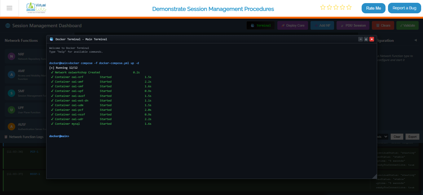
Fig: Terminal output showing core network deployment with docker compose
Deploy gNB (Base Station) Services
Once your core network is up and running, it's time to deploy the gNB (Base Station). This command spins up the gNB containers and establishes the connection between the gNB and your core network, so they can start communicating with each other.
docker compose -f docker-compose-gnb.yml up -d
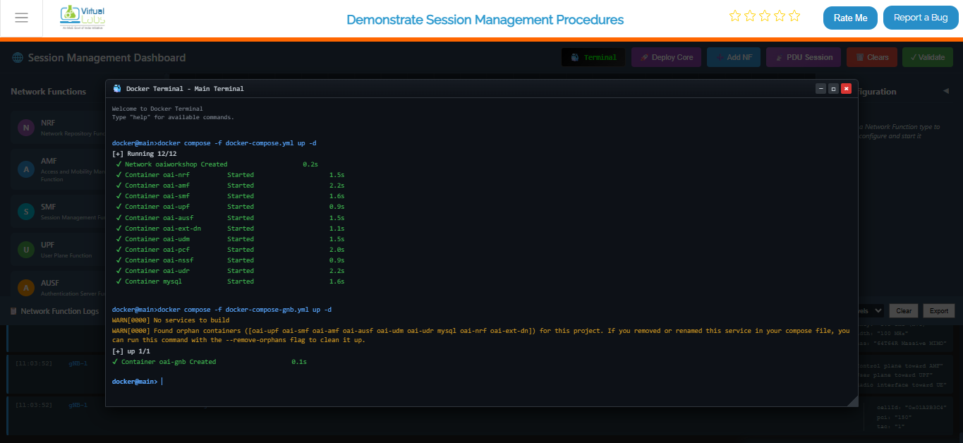
Fig: Terminal output showing gNB deployment and connection to core network
Deploy UE (User Equipment) Services
This command starts up the UE (User Equipment) containers and connects them to the gNB. The UEs are essentially the "phones" or "devices" in your 5G network simulation.
docker compose -f docker-compose-ue.yml up -d
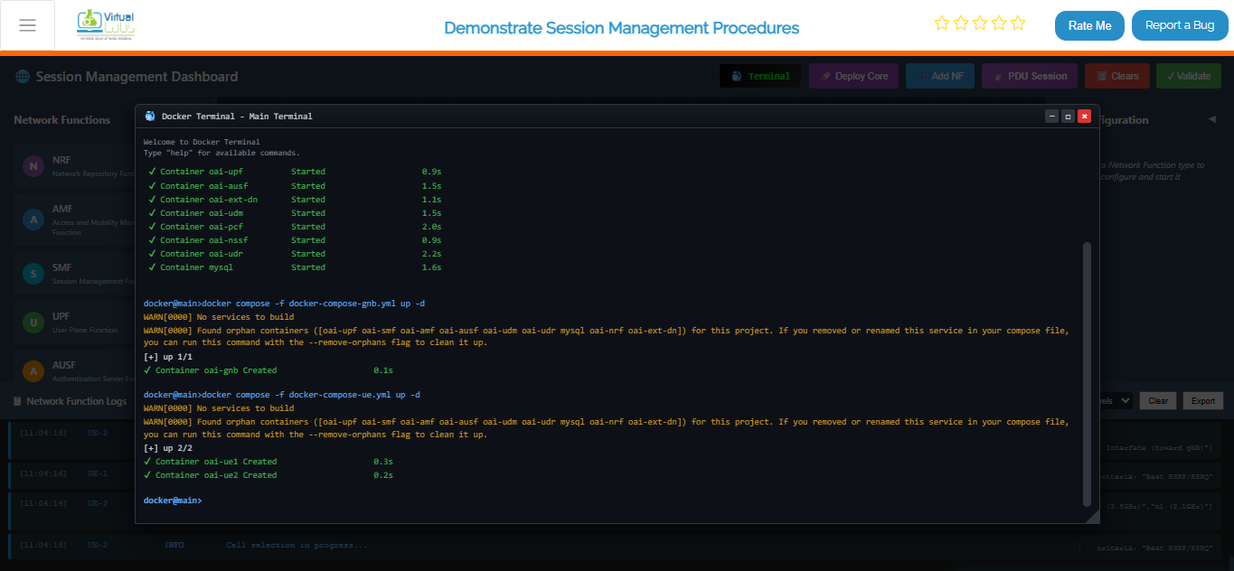
Fig: Terminal output showing UE deployment and attachment to gNB
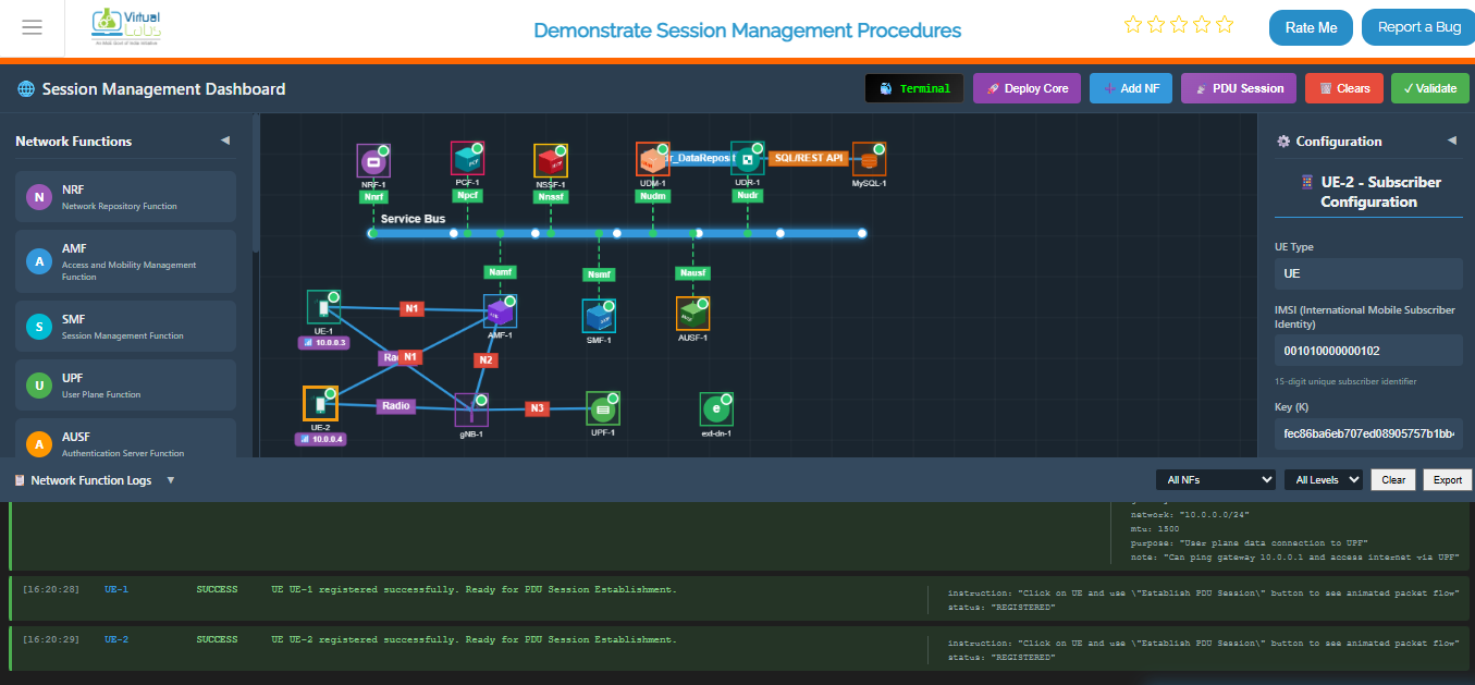
Fig: Complete 5G network topology with UE, gNB, and all core network functions running
View All Running Containers
This command shows you a complete list of all containers that Docker is currently running — including their IDs, status, and names. "
docker ps
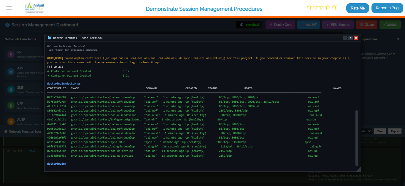
Fig: Docker PS output listing all running 5G network containers with their status
Live Monitoring Dashboard for Core Network
This command shows you the real-time status of all your core network containers.
watch docker compose -f docker-compose.yml ps -a
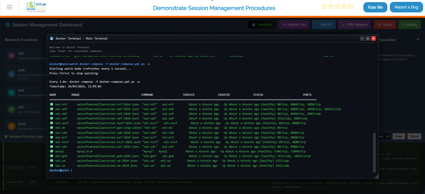
Fig: Continuous real-time monitoring of core network container status
Option B (Automatic): Click the Deploy Core button on the top toolbar. This will automatically clear any existing topology and sequentially deploy the Service Buses, Network Functions (NRF, AMF, SMF, UPF, UDR, PCF, gNB, UE), and establish the necessary connections.
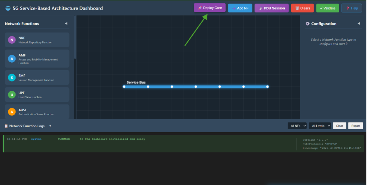
Fig: One Click Core Network Deployment
Option C (Manual): Manually add each Network Function from Network function panel then enter configuration detail in the left configuration panel and start NF.
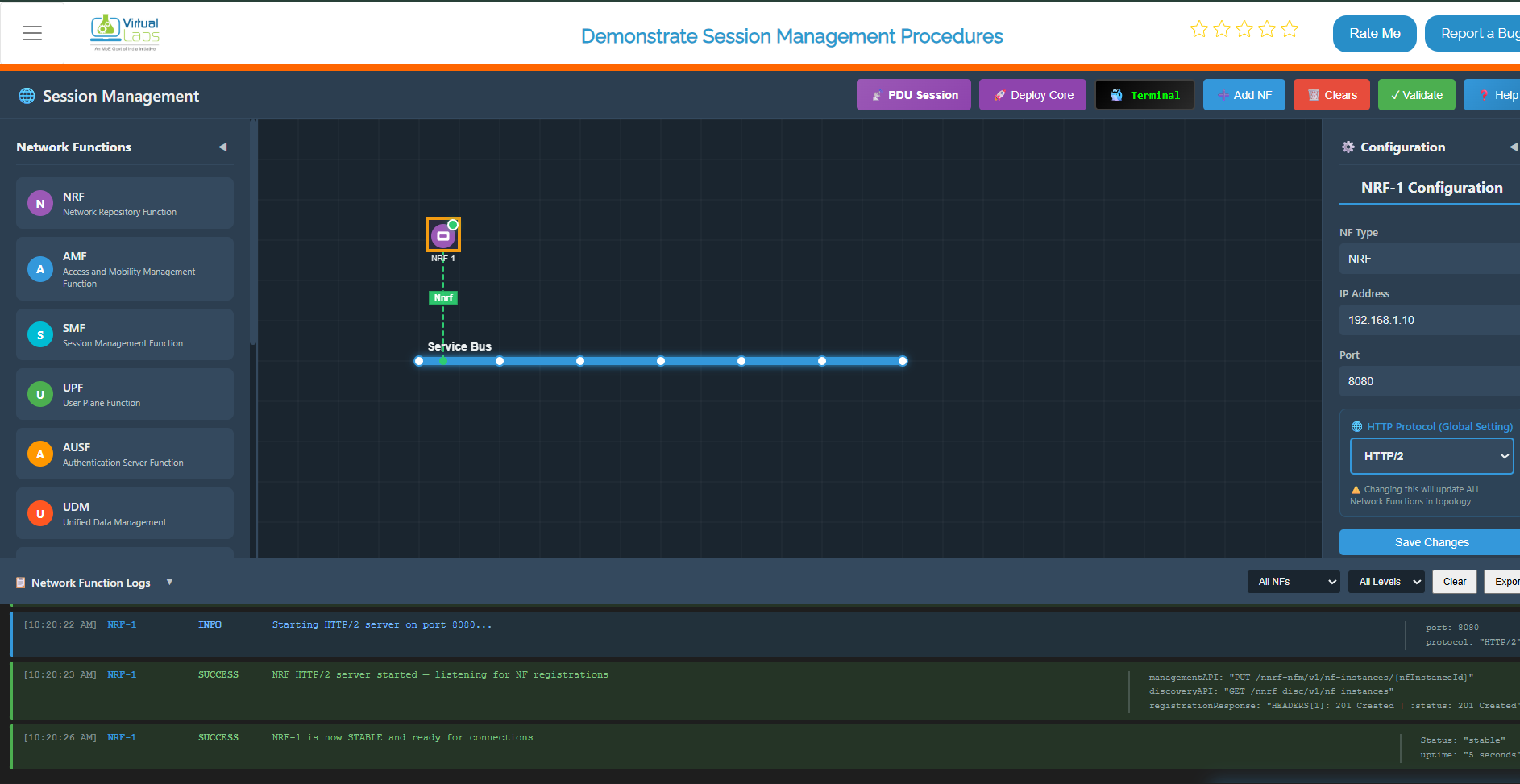
Fig: Core Network Deployment
Step 2: Enable PDU Session Mode
Once the core network is successfully deployed and all NFs show a "Stable" status, click on the PDU Session button in the top toolbar to switch the interface to the Session Management experiment mode.
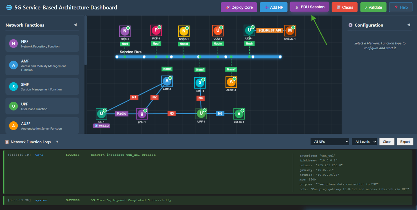
Fig: PDU Session Mode
Step 3: Observe Experiment Panels
You will now see:
- Right Panel (PDU Session Establishment): A step-by-step interactive flow for the PDU session creation process.
- Left Panel (PDU Session Messages): An inspector panel that displays the JSON content of every Request and Response message sent between NFs.
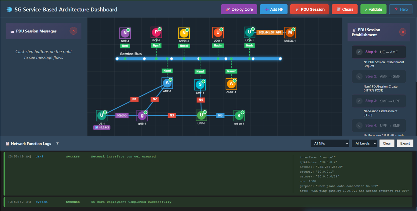
Fig: Experiment Panels
Step 4: UE Requests Session
Click Step 1 in the right panel.
- Action: UE sends a PDU Session Establishment Request to the AMF via N1 interface.
- Observation: A packet travels from UE to AMF. The left panel shows the NAS message details including supi, dnn, and requestType.
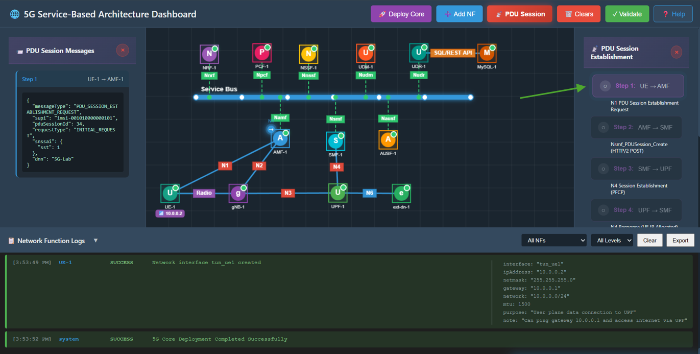
Fig: UE Session Request
Step 5: AMF Selects SMF
Click Step 2 in the right panel.
- Action: AMF forwards the request to the SMF by sending Nsmf_PDUSession_Create.
- Observation: A packet travels from AMF to SMF. The left panel verifies that AMF has selected an SMF.
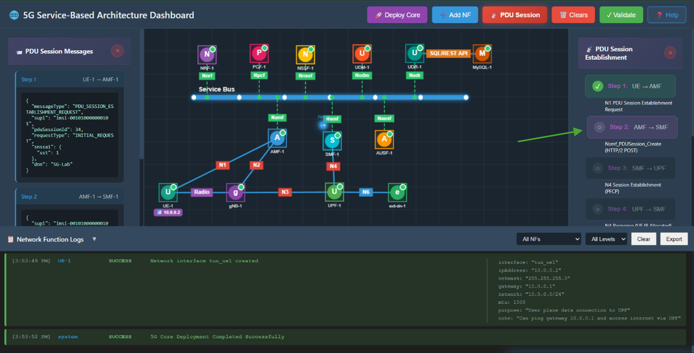
Fig: AMF Selects SMF
Step 6: SMF Configures UPF
Click Step 3 in the right panel.
- Action: SMF instructs the UPF to establish a user plane session via N4 Session Establishment Request.
- Observation: A packet travels from SMF to UPF. This requests resource allocation on the User Plane.
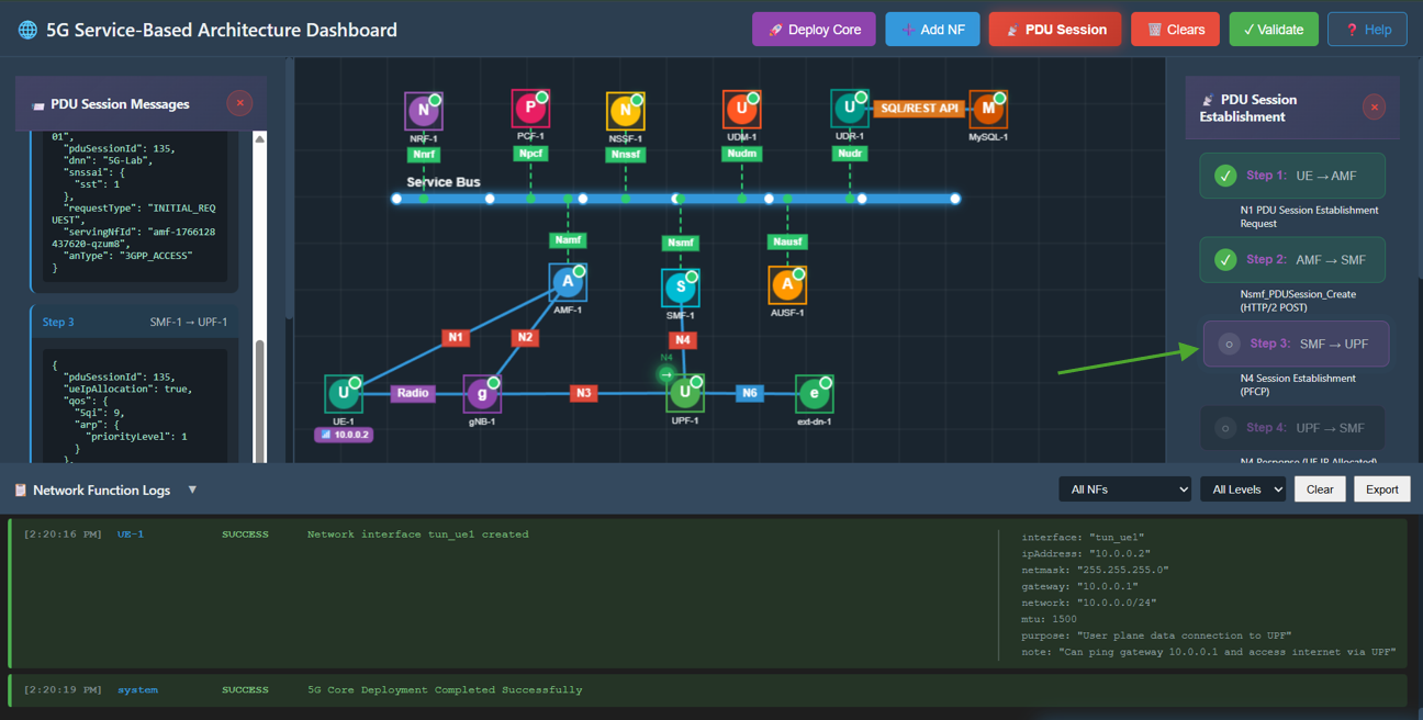
Fig: SMF Configures UPF
Step 7: UPF Allocates IP
Click Step 4 in the right panel.
- Action: UPF processes the request, allocates an IP address for the UE, and sends an N4 Session Establishment Response back to the SMF.
- Observation: A packet travels from UPF to SMF. The response JSON contains the assigned ueIp and tunnelId.
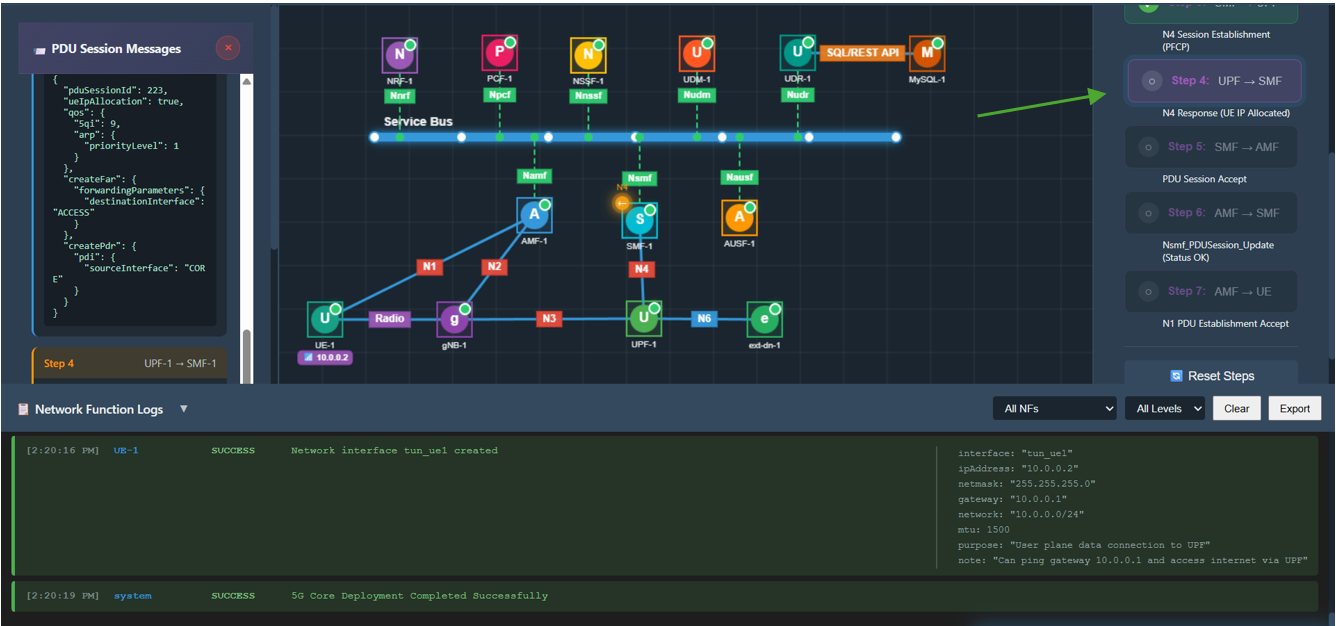
Fig: UPF Allocates IP
Step 8: SMF Accepts Session
Click Step 5 in the right panel.
- Action: SMF sends a Nsmf_PDUSession_Create Response back to the AMF, confirming the session is ready.
- Observation: A packet travels from SMF to AMF. The message includes QoS rules and the allocated IP address.
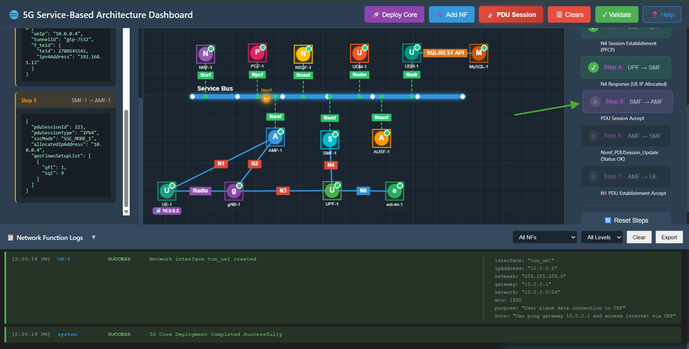
Fig: SMF Accepts Session
Step 9: AMF Updates SMF
Click Step 6 in the right panel.
- Action: AMF sends a Nsmf_PDUSession_Update message to the SMF to confirm the status is active and resources are ready.
- Observation: A packet travels from AMF to SMF. The message confirms Status: Active.
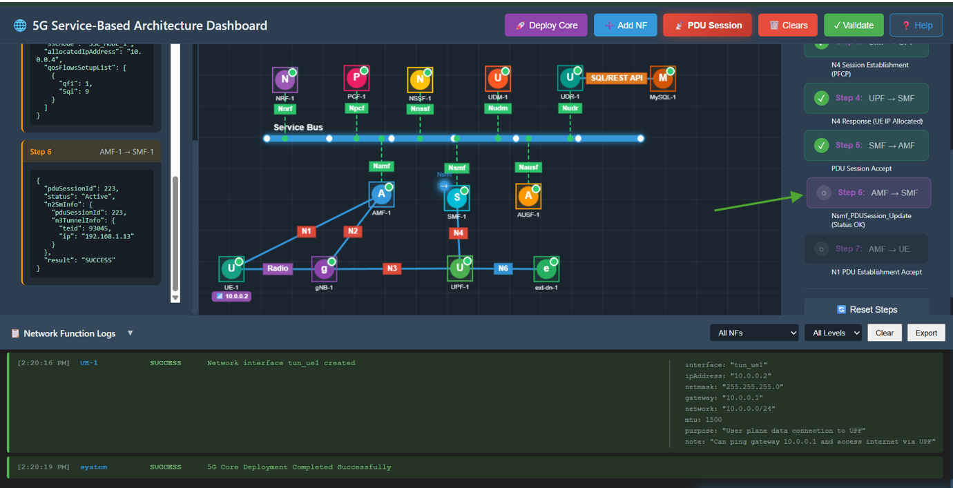
Fig: AMF Updates SMF
Step 10: AMF Notifies UE
Click Step 7 in the right panel.
- Action: AMF sends the final PDU Session Establishment Accept message to the UE.
- Observation: A packet travels from AMF to UE. The UE receives its IP address (10.0.0.x) and the PDU Session is marked as Established.
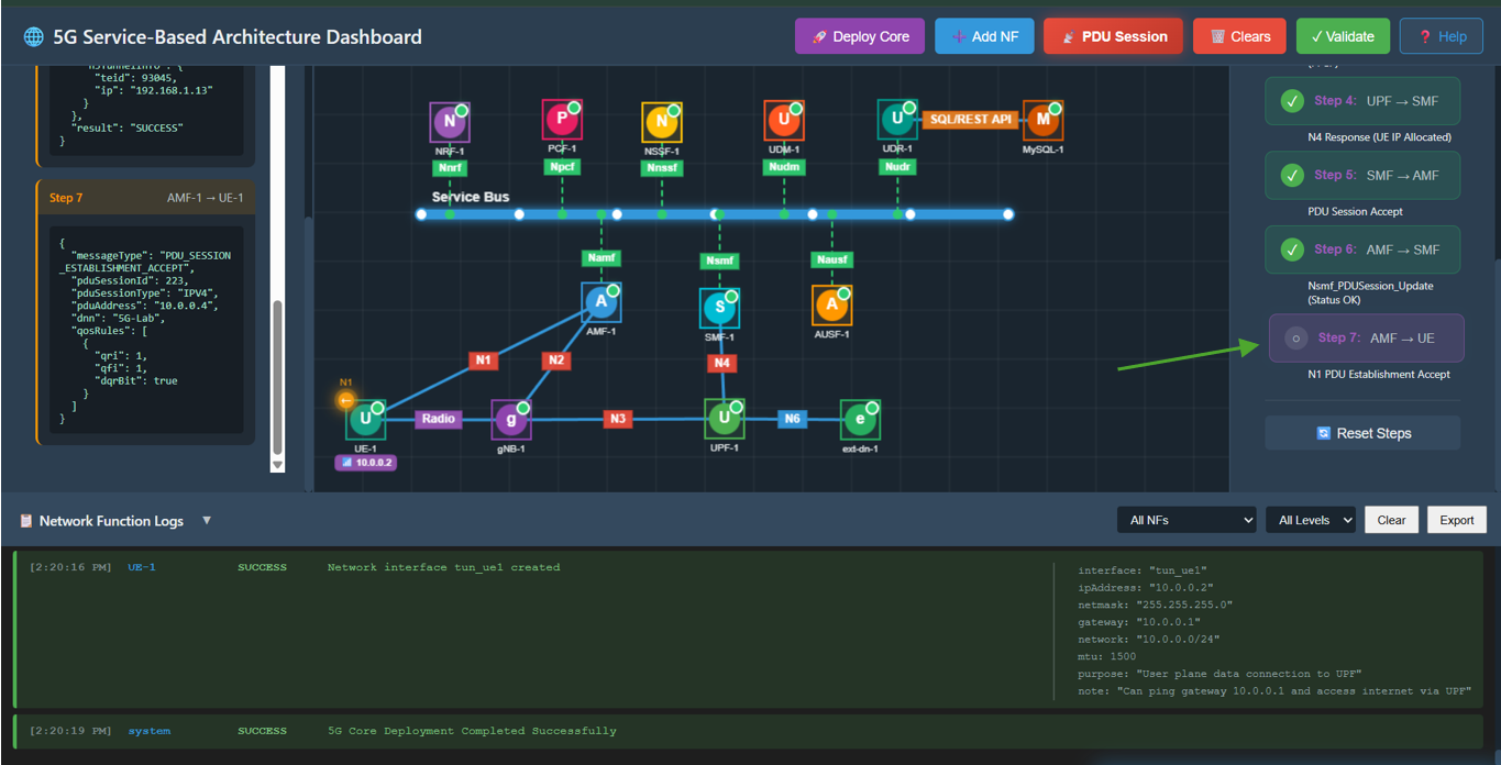
Fig: AMF Notifies UE