
Demonstrate Registration Management Procedures
Video Walkthrough: We have created a video demonstrating this experiment where we perform the procedure and explain the steps. Click here to watch on YouTube
Step 1: Deploy Core Network
Choose one of the following deployment options:
Option A (Docker-Terminal):
Click on the Docker Terminal button to open the terminal then from the project root directory, execute the following command:
This command starts all core network components (AMF, SMF, UPF, NRF, etc.) in detached mode
docker compose -f docker-compose.yml up -d
Command Description:
docker compose- Docker Compose tool for managing multi-container applications-f docker-compose.yml- Specifies the compose file to use (default configuration for core network)up- Creates and starts all services defined in the compose file-d- Runs containers in detached mode (background), allowing the terminal to remain usable
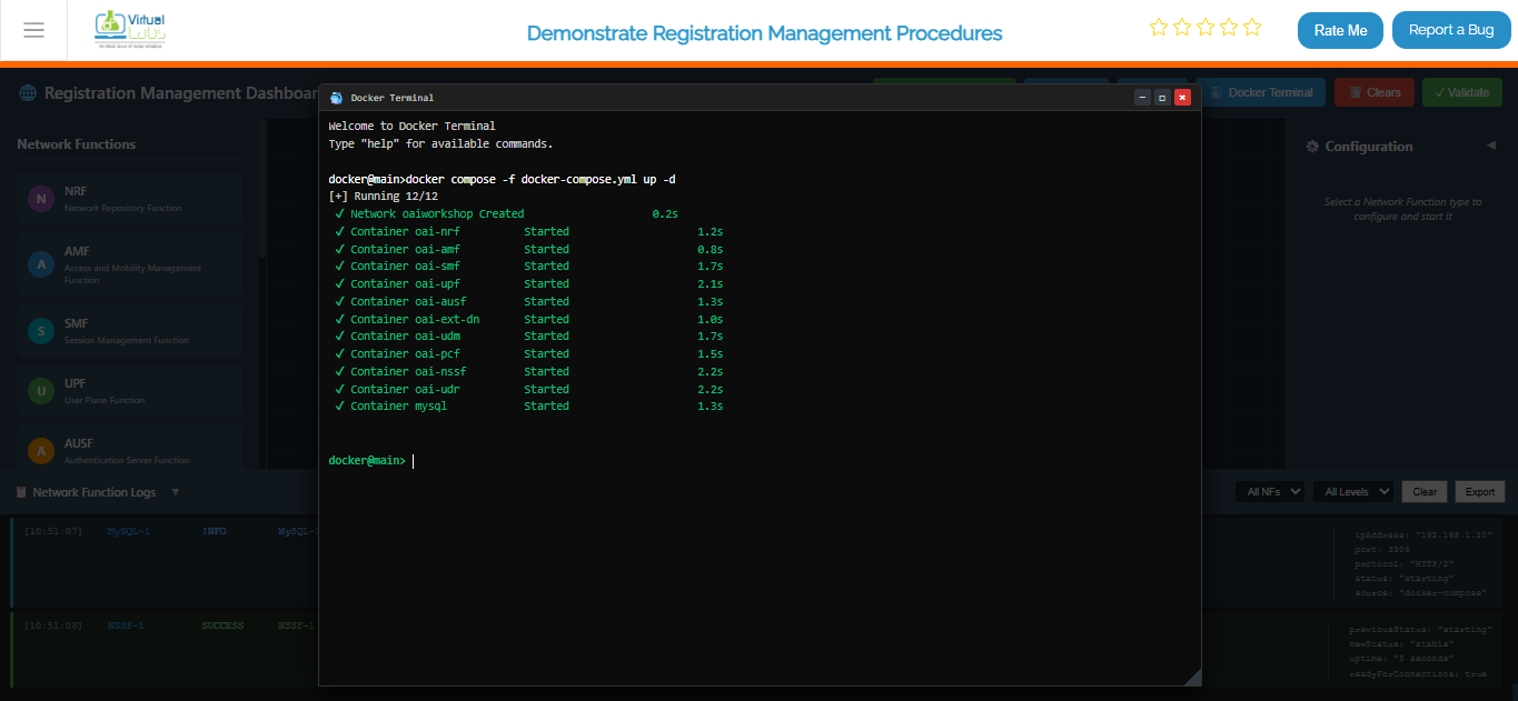
Fig: Terminal output showing core network deployment with docker compose
Once the core network is up and running, deploy the gNB services:
This command initializes the gNB and establishes connectivity with the core network.
docker compose -f docker-compose-gnb.yml up -d
Command Description:
docker compose- Docker Compose tool for managing multi-container applications-f docker-compose-gnb.yml- Specifies the gNode B compose configuration fileup- Creates and starts all gNB-related services-d- Runs in detached mode (background)
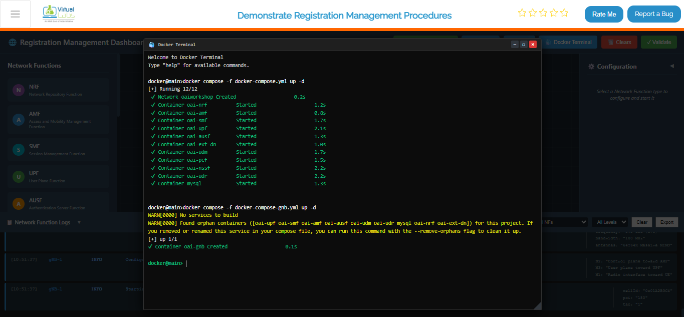
Fig: Terminal output showing gNB deployment and connection to core network
After the gNB deployment is complete, deploy the UE services:
This starts the UE containers and attaches them to the gNB.
docker compose -f docker-compose-ue.yml up -d
Command Description:
docker compose- Docker Compose tool for managing multi-container applications-f docker-compose-ue.yml- Specifies the User Equipment compose configuration fileup- Creates and starts all UE-related services-d- Runs in detached mode (background)
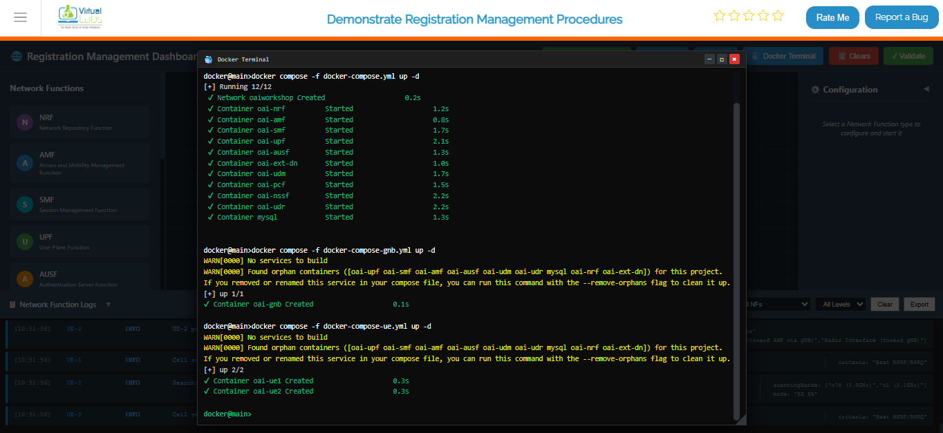
Fig: Terminal output showing UE deployment and attachment to gNB
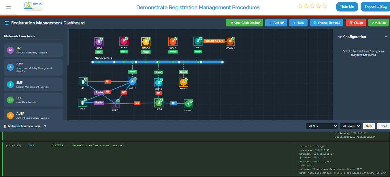
Fig: Complete end-to-end 5G network topology with UE, gNB, and core network fully connected
To verify that all containers are running successfully, execute:
docker ps
Command Description:
docker ps- Lists all currently running containers- Shows container ID, image name, status, ports, and other metadata
- Useful for verifying all services are up and running
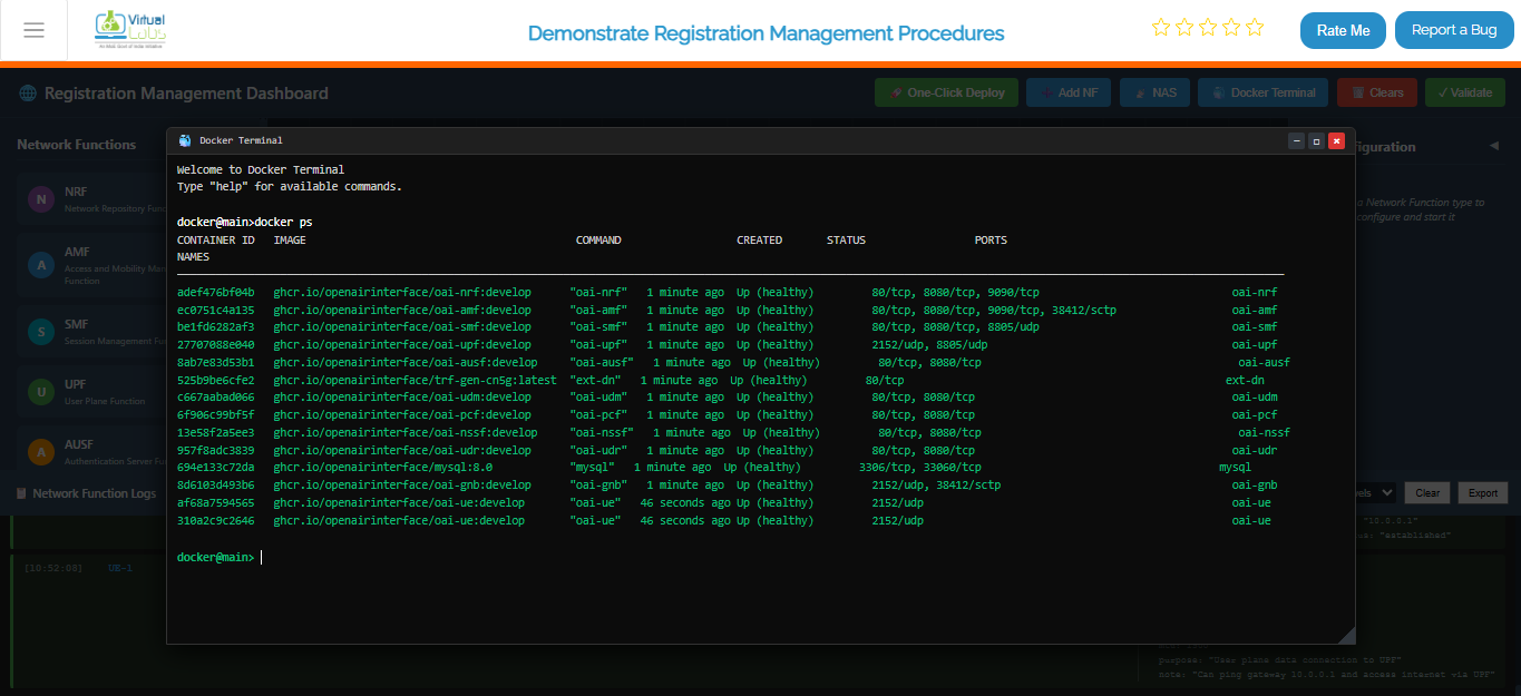
Fig: Docker PS output listing all running 5G network containers with their status
To continuously monitor the status of the core network containers, use:
This command provides real-time monitoring of the core network deployment.
watch docker compose -f docker-compose.yml ps -a
Command Description:
watch- Repeats a command at regular intervals (default: 2 seconds)docker compose- Docker Compose tool-f docker-compose.yml- Specifies the core network compose fileps- Shows process/container status-a- Shows all containers (including stopped ones)
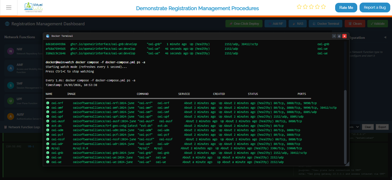
Fig: Continuous monitoring view showing live status of all core network containers
Option B (Automatic - Recommended):
- Click the One-Click Deploy button on the top toolbar.
- Confirm the deployment when prompted.
- Observation: The system will automatically clear any existing topology and sequentially deploy the Service Bus, then all Network Functions (NRF, AMF, SMF, UPF, AUSF, UDM, PCF, NSSF, UDR, MySQL, gNB, UE, ext-dn), and establish the necessary connections. NFs will appear one by one.
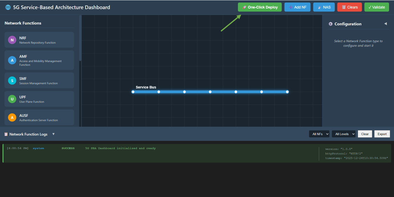
Fig:Automatic one-click core network deployment
Option C (Manual):
Manually add each Network Function from the Network Function panel, then enter configuration details in the left configuration panel and start the NF.
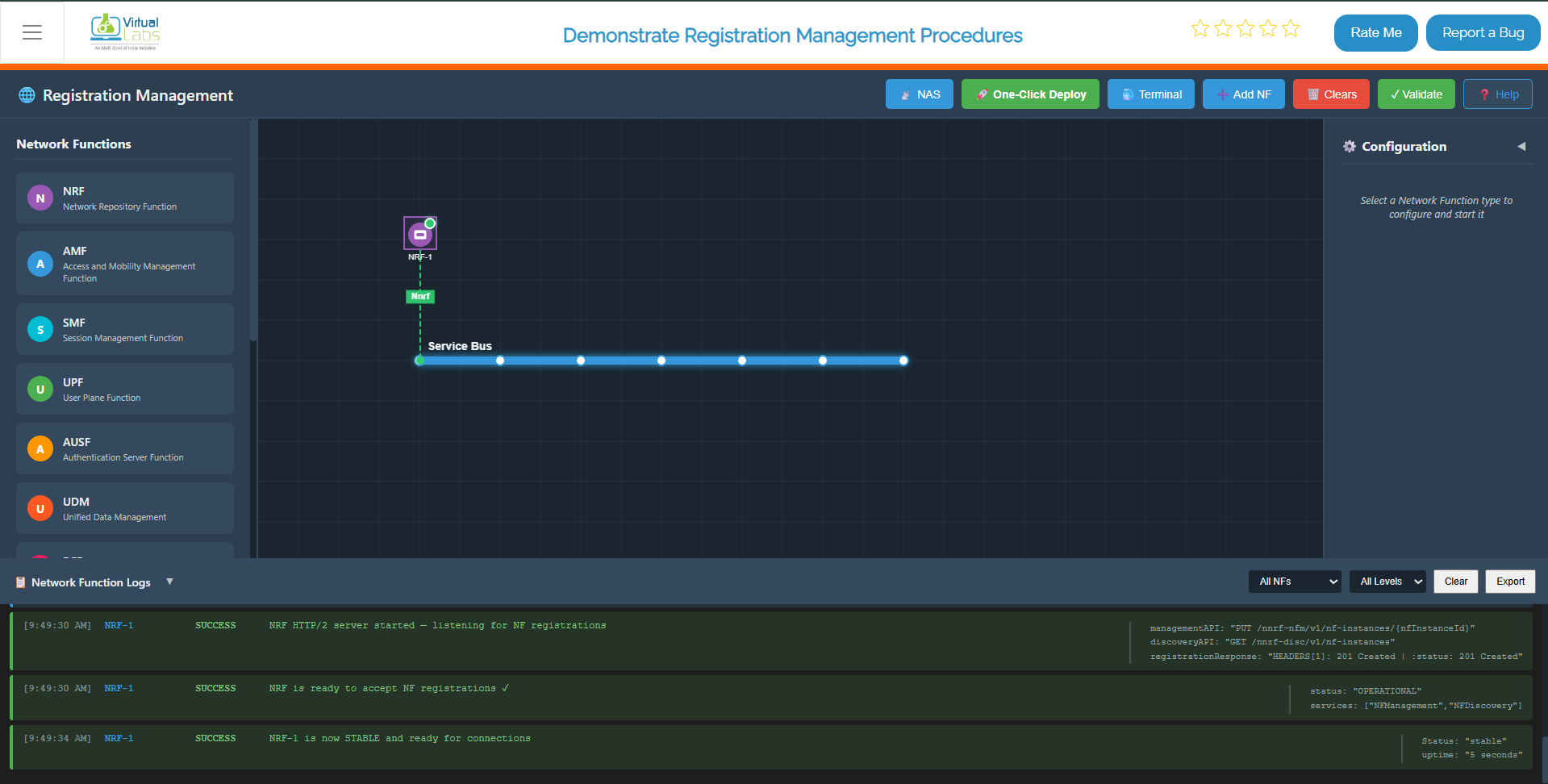
Fig: Core Network Deployment
Step 2: Enable NAS Registration Mode
Once the core network is successfully deployed (wait for the "One-Click Topology Deployed!" alert):
- Click on the NAS button in the top toolbar to switch the interface to the NAS Registration experiment mode.
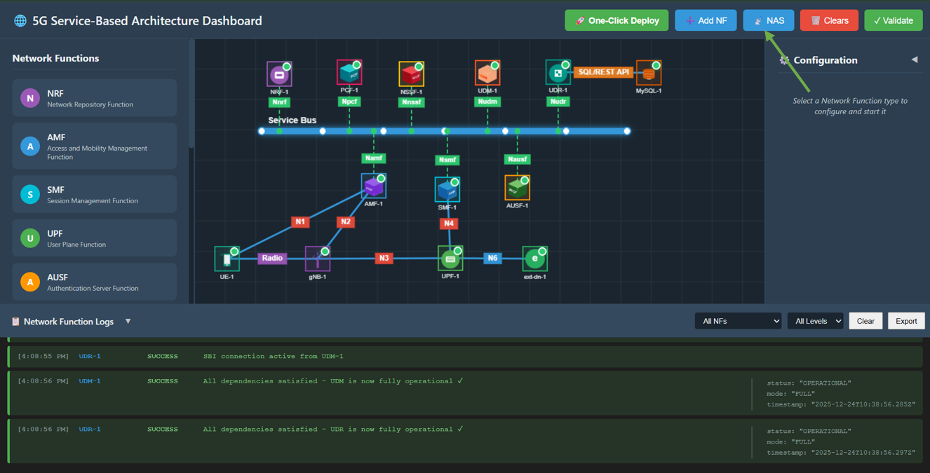
Fig: Enable NAS Registration Mode
Step 3: Observe Experiment Panels
You will now see the interface transform:
- Right Panel (NAS Registration Process): A list of 13 interactive steps representing the registration flow.
- Left Panel (NAS Messages): An inspector panel that displays the JSON content of every NAS message sent between NFs.
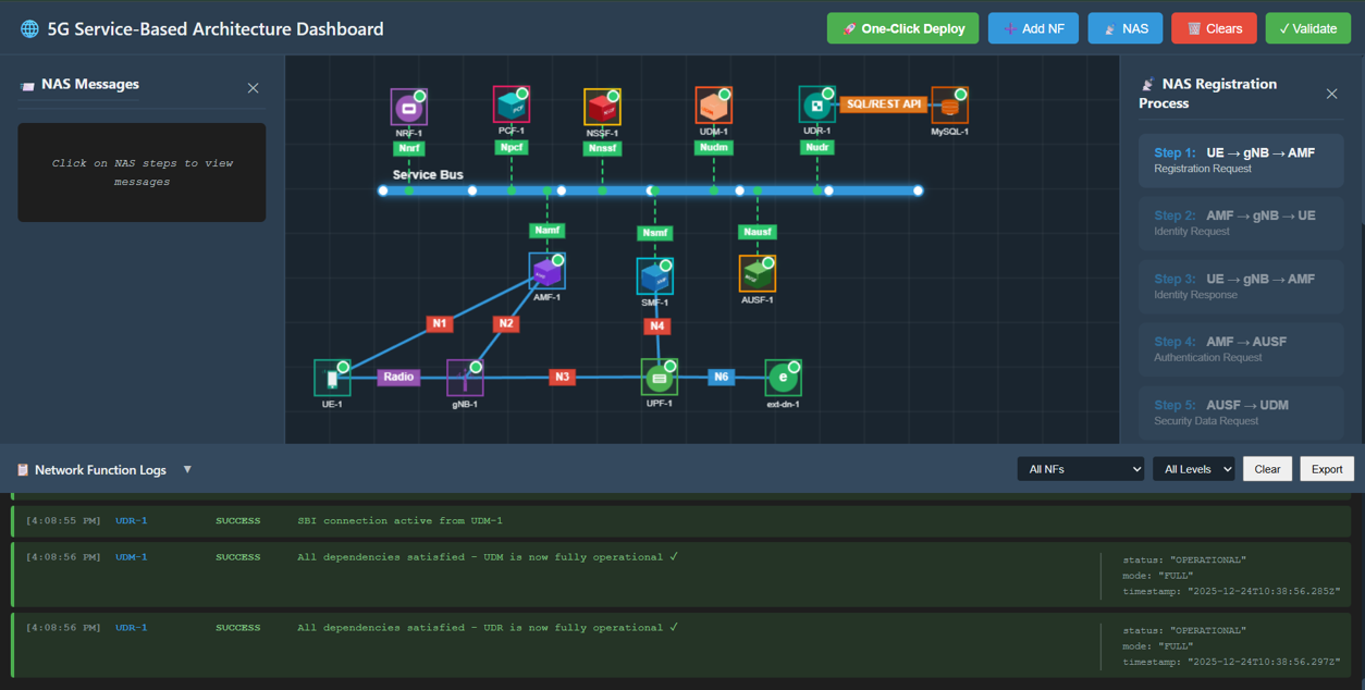
Fig: Experiment Panels Overview
Step 4: Perform Registration Procedure
Follow the steps in the right panel sequentially. Click each step button to execute the action.
Step 4.1: Registration Request
Action: Click Step 1: UE → gNB → AMF in the right panel.
Description: UE sends a Registration Request to the AMF via the gNB.
Observation: A packet travels from UE to gNB, then to AMF. The left panel displays the JSON message containing the RegistrationRequest with SUCI (Subscription Concealed Identifier).
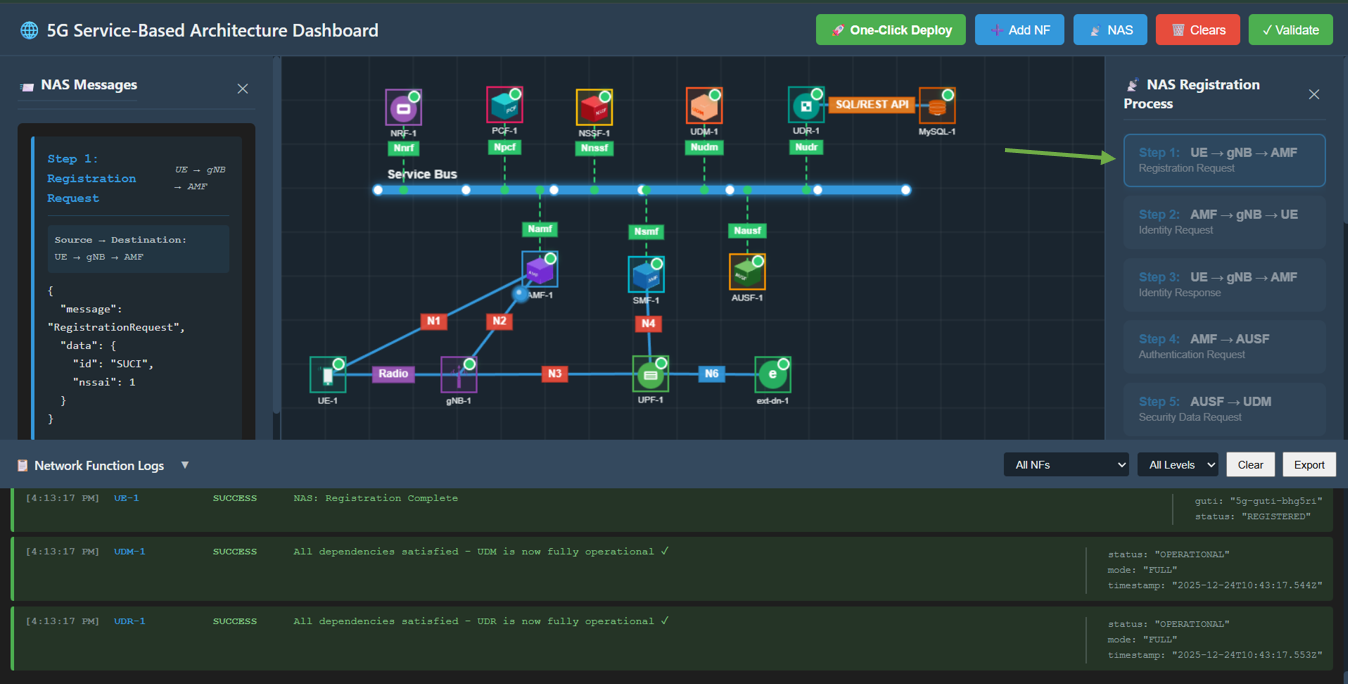
Fig: Step 1: Registration Request
Step 4.2: Identity Request
Action: Click Step 2: AMF → gNB → UE.
Description: AMF requests the UE's identity.
Observation: A packet travels from AMF to gNB, then to UE. The JSON message shows IdentityRequest.
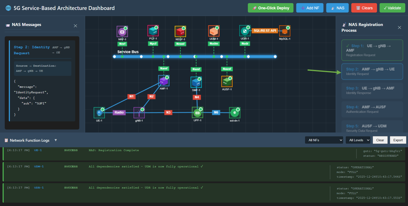
Fig: Step 2: Identity Request
Step 4.3: Identity Response
Action: Click Step 3: UE → gNB → AMF.
Description: UE responds with its identity (SUPI/IMSI).
Observation: A packet travels from UE back to AMF. The JSON message contains the IdentityResponse with supi.
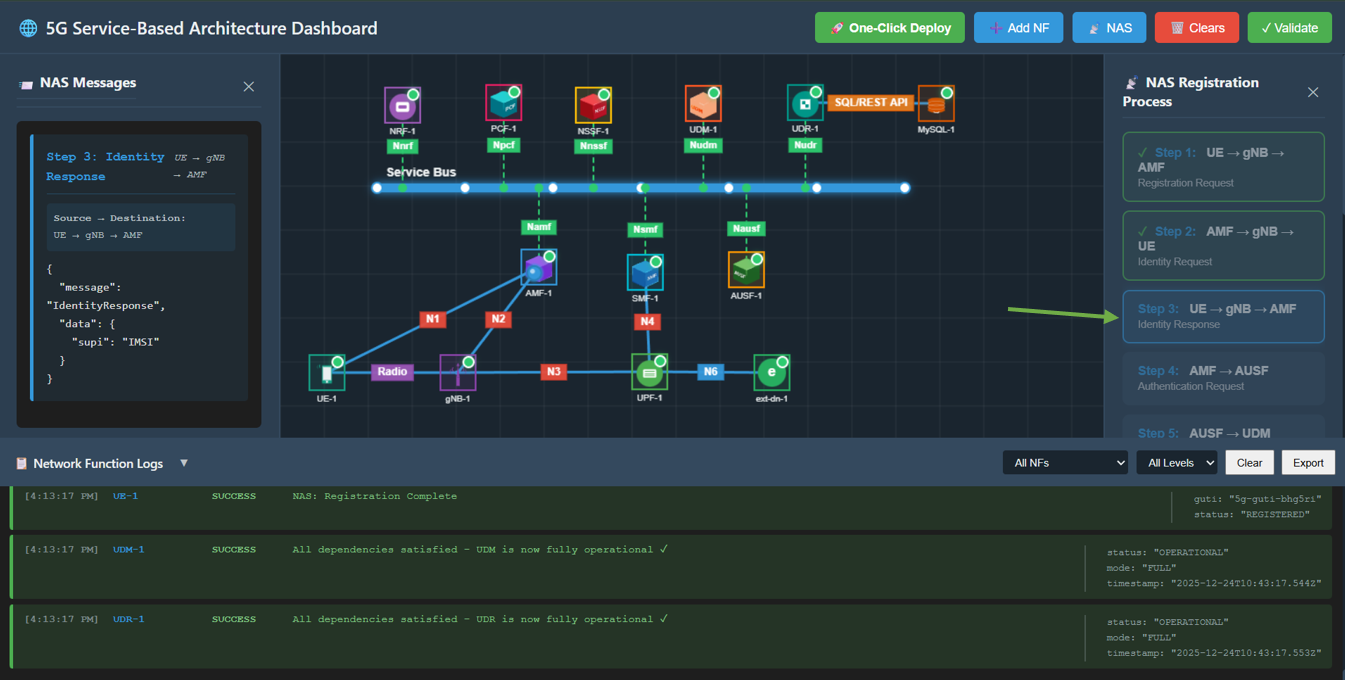
Fig: Step 3: Identity Response
Step 4.4: Authentication Request
Action: Click Step 4: AMF → AUSF.
Description: AMF initiates authentication with the AUSF (Authentication Server Function).
Observation: A packet travels from AMF to AUSF. The JSON message shows AuthenticationRequest using 5G-AKA.
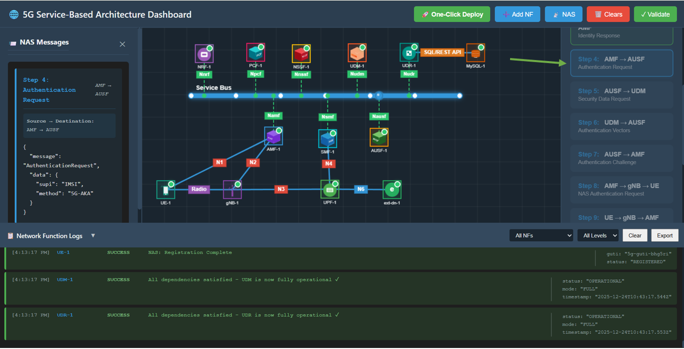
Fig: Step 4: Authentication Request
Step 4.5: Security Data Request
Action: Click Step 5: AUSF → UDM.
Description: AUSF requests security data from the UDM (Unified Data Management).
Observation: A packet travels from AUSF to UDM.
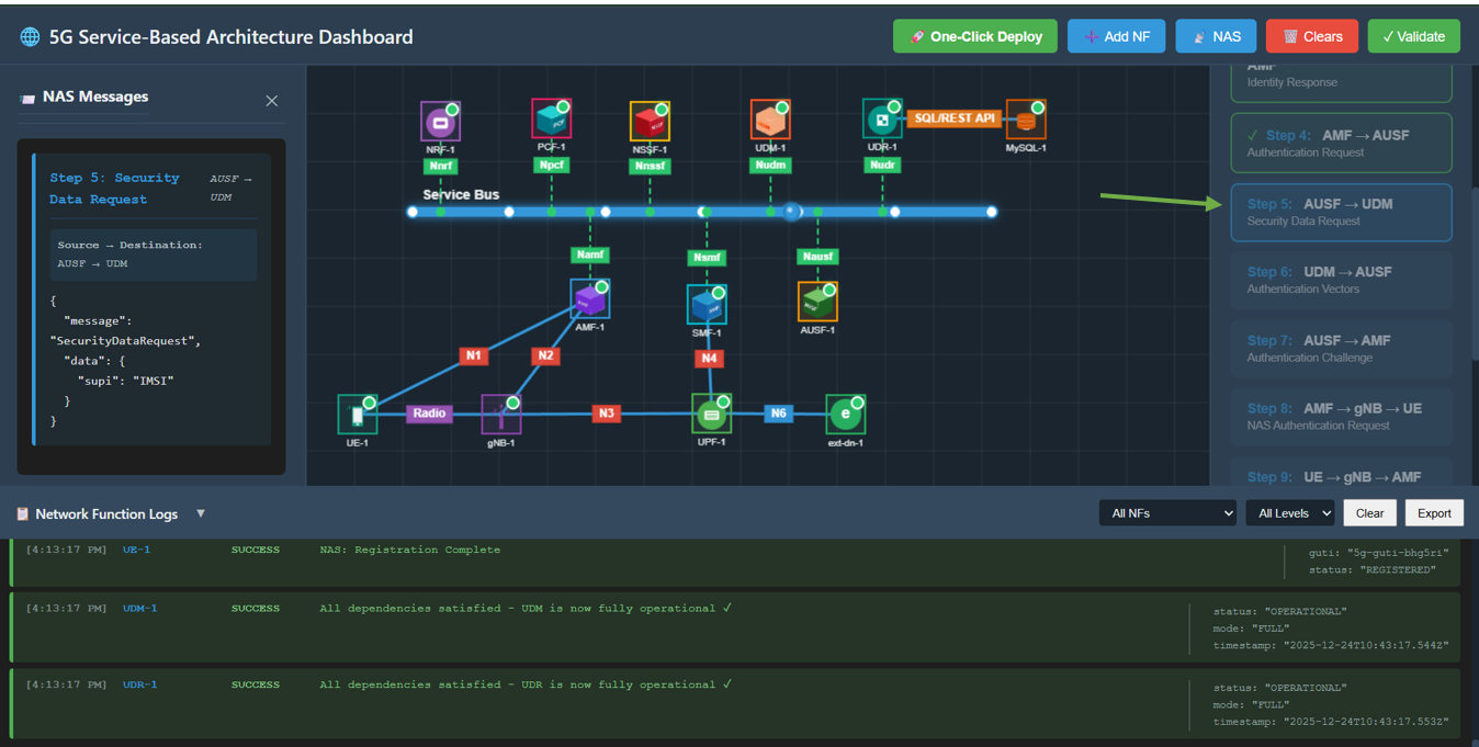
Fig: Step 5: Security Data Request
Step 4.6: Authentication Vectors
Action: Click Step 6: UDM → AUSF.
Description: UDM generates and sends authentication vectors to AUSF.
Observation: Packet travels from UDM to AUSF. Message contains AuthenticationVectors (RAND, AUTN).
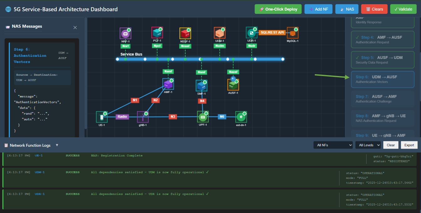
Fig: Step 6: Authentication Vectors
Step 4.7: Authentication Challenge
Action: Click Step 7: AUSF → AMF.
Description: AUSF forwards the authentication challenge to the AMF.
Observation: Packet travels from AUSF to AMF.
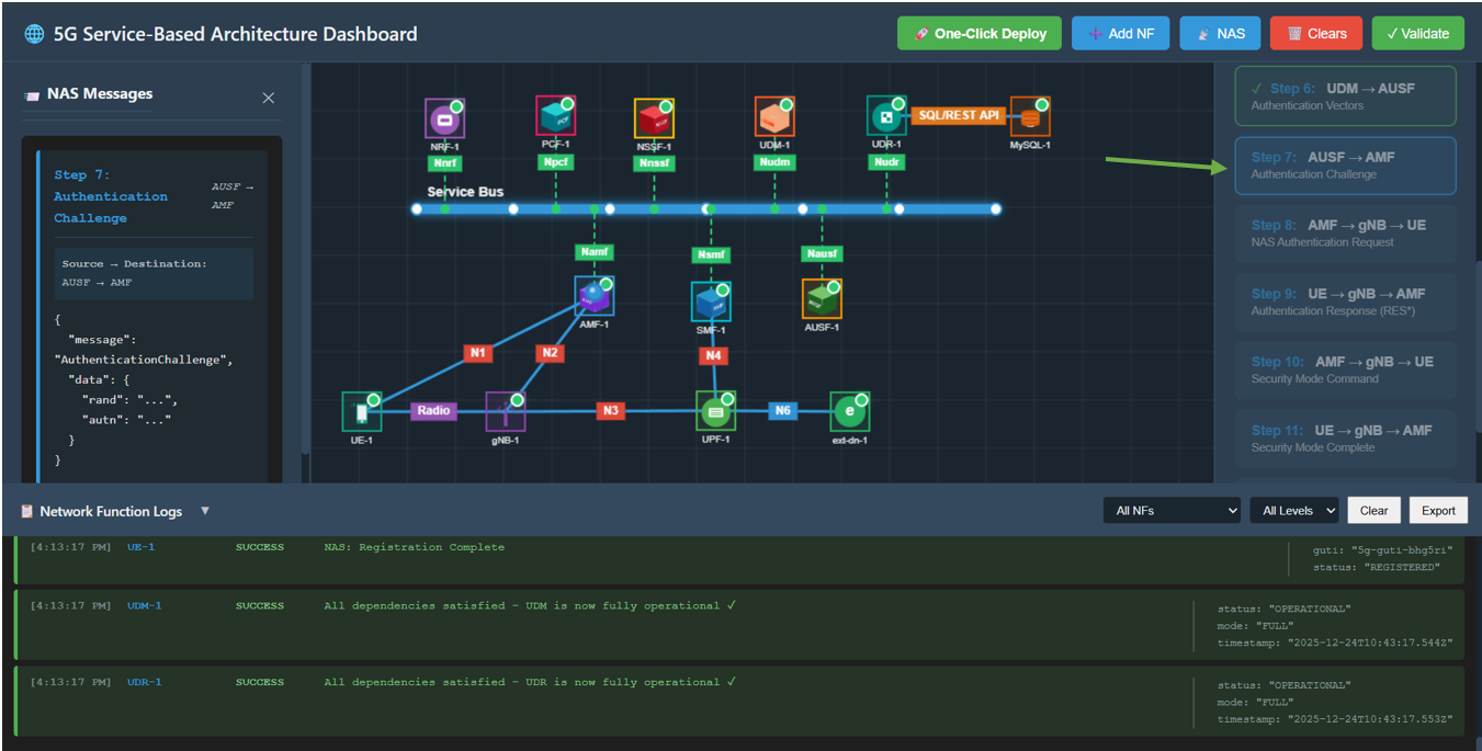
Fig: Step 7: Authentication Challenge
Step 4.8: NAS Authentication Request
Action: Click Step 8: AMF → gNB → UE.
Description: AMF challenges the UE to authenticate itself.
Observation: Packet travels from AMF to UE. Message is NASAuthenticationRequest.
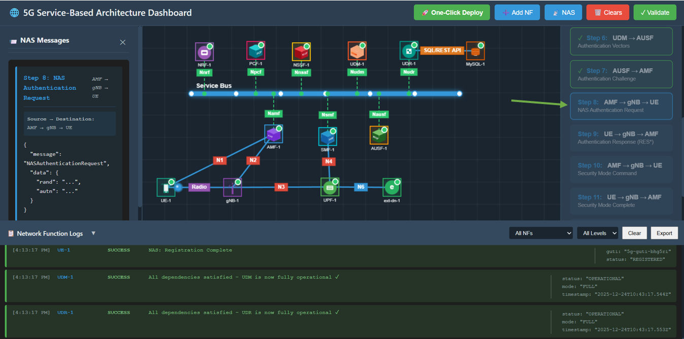
Fig: Step 8: NAS Authentication Request
Step 4.9: Authentication Response
Action: Click Step 9: UE → gNB → AMF.
Description: UE computes the response (RES*) and sends it back to AMF.
Observation: Packet travels from UE to AMF. Message contains AuthenticationResponse.
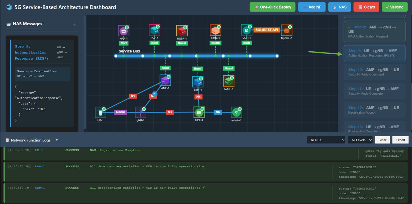
Fig: Step 9: Authentication Response
Step 4.10: Security Mode Command
Action: Click Step 10: AMF → gNB → UE.
Description: AMF creates a secure context and commands the UE to enable security.
Observation: Packet travels from AMF to UE. Message contains SecurityModeCommand (ciphering/integrity algorithms).
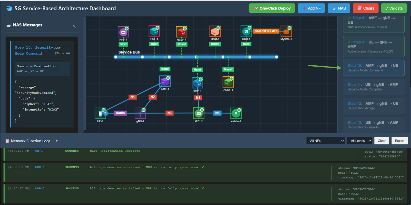
Fig: Step 10: Security Mode Command
Step 4.11: Security Mode Complete
Action: Click Step 11: UE → gNB → AMF.
Description: UE confirms security is active.
Observation: Packet travels to AMF. Message is SecurityModeComplete.
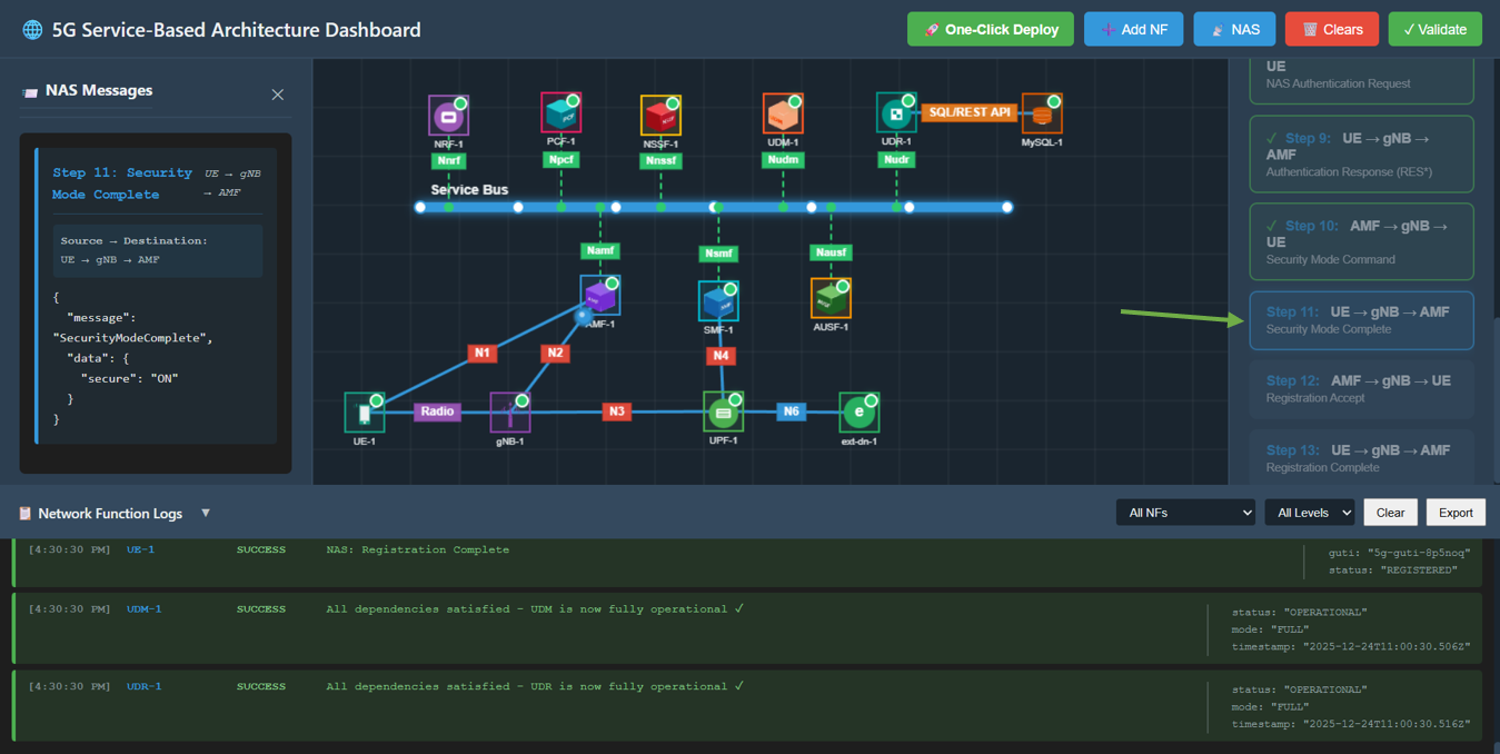
Fig: Step 11: Security Mode Complete
Step 4.12: Registration Accept
Action: Click Step 12: AMF → gNB → UE.
Description: AMF accepts the registration and assigns a temporary ID (5G-GUTI).
Observation: Packet travels to UE. Message is RegistrationAccept containing 5G-GUTI.
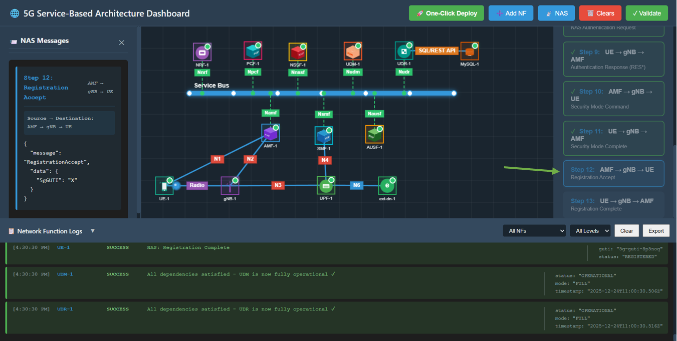
Fig: Step 12: Registration Accept
Step 4.13: Registration Complete
Action: Click Step 13: UE → gNB → AMF.
Description: UE acknowledges the registration is complete.
Observation: Packet travels to AMF. Message is RegistrationComplete with status OK.
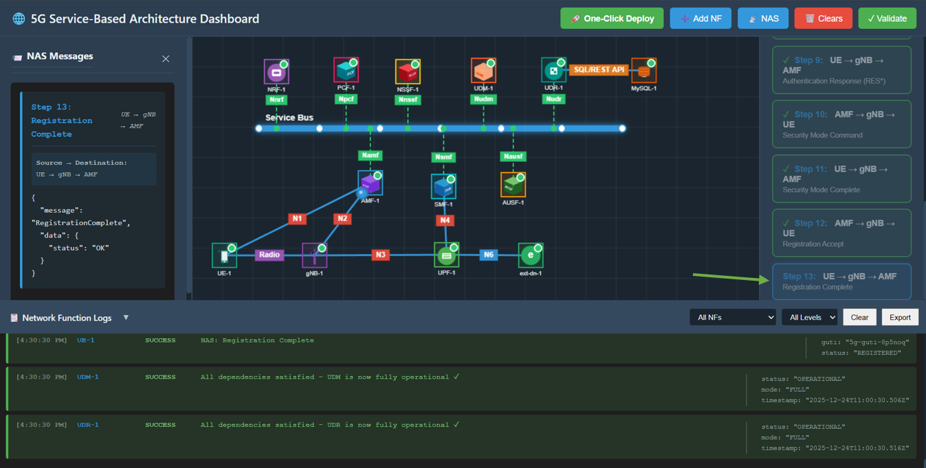
Fig: Step 13: Registration Complete